Perforated cup flow dynamics
🎶 Music recommendation: Queens Of The Stone Age - Go With The Flow
1 Introduction
Kids bring you many things: can be smile and happy moments but also hydraulic problems. This post about the last one. So, seeing him playing in his bath with perforated cups, I started wondering how much time it takes for the water to entirely leave the cup. And also what is the flowrate at the hole and how fast does the water level decreases.
2 Derivation of the liquid height over time equation
Being a naive chemical engineer I started doing what I know best: a drawing and some mass balances. And Bernoulli equation because I had a flash about this one.
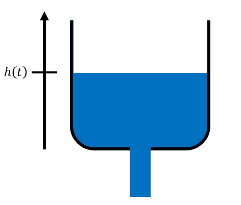
Figure 2.1: Cup sketch
So basically the mass balance on the system is the following:
\[\begin{equation} \frac{dh}{dt} \times S = -\dot{Q}_1 = -v_1\left(t\right) \times s \tag{2.1} \end{equation}\]with:
- \(h\) the height of the liquid at a given instant
- \(\dot{Q}_1\) the fluid flowrate at the cup hole
- \(v_1\) the fluid velocity at the cup hole
- \(S\) and \(s\) respectively the surface of liquid in contact with air at the top of the cup and the section of the hole. In order to avoid instant evacuation of the cup, one should have \(s<S\).
The negative signs are here to account for the decrease of the liquid height over time.
Ok, this is a starting point but this equation has a \(v_1\) term that I do not know (because I want to calculate it). So let us invoke Bernoulli equation between the fluid surface (indexed 2) and the cup hole (indexed 1):
\[\begin{equation} P_1 + \rho g h_1 + \frac{1}{2}\rho v_1^2 = P_2 + \rho g h_2 + \frac{1}{2}\rho v_2^2 \tag{2.2} \end{equation}\]with the terms:
- \(P_1\) is equal to atmospheric pressure. I was not convinced initially but I came to this conclusion considering that if the stream pressure at the cup hole was different from the atmospheric pressure the outlet stream should either contract or expand. I took a look at the stream after the hole and did not observe this behavior so I believe this approximation is quite acceptable. Yet I would like a more sound explanation (could some internal energy/temperature variation around the hole exist? - this term was neglected in the Bernoulli equation).
- \(P_2\) is equal to atmospheric pressure as it is in contact with the atmosphere. I believe that some gaseous water molecules are also present above the liquid surface (saturation pressure) but that their number is so small that it does not contribute significantly to change the pressure applied on top of the liquid surface (from a thermodynamic point of view the system to study would be described as a pseudo-binary system water/air).
- \(h_1\) can be arbitrarily set to 0 as I am free to chose the origin of my working referential.
- \(h_2\) is basically \(h\) (less indexes!)
- \(v_1\) is the unknown from my mass balance equation. So now I believe that I should be able to use this equation to calculate it.
- \(v_2\) is the velocity of the liquid interface and is by definition the derivative of \(h\) with respect to time (i.e., \(dh/dt\))
So the Bernoulli equation now becomes:
\[\begin{equation} \frac{1}{2}\rho v_1^2 = \rho g h + \frac{1}{2}\rho \left(\frac{dh}{dt}\right)^2 \tag{2.3} \end{equation}\]So, extraction the \(v_1\) expression from the mass balance and injecting its expression in the Bernoulli equation, one gets:
\[\begin{equation} \frac{1}{2}\rho \left(\frac{S}{s}\times\frac{dh}{dt}\right)^2 = \rho g h + \frac{1}{2}\rho \left(\frac{dh}{dt}\right)^2 \tag{2.4} \end{equation}\]Some mathematical rearrangements lead to:
\[\begin{equation} \left(\frac{dh}{dt}\right)^2 \times \left(1 - \frac{S^2}{s^2}\right) + 2gh = 0 \tag{2.5} \end{equation}\]Finally, the differential equation to solve to obtain the expression of \(h\) over time is:
\[\begin{equation} \frac{dh}{dt} = -\sqrt{\frac{2gh}{\left(\frac{S^2}{s^2}-1\right)}} \tag{2.6} \end{equation}\]Notice that there are in fact two possible expressions for \(dh/dt\): one with a minus in front of the square root and one with a plus signal in front of the square root. But because \(h\) must decrease over time, only the expression with the negative sign corresponds to the described situation.
Then we split the variables to perform the integration:
\[\begin{equation} \frac{dh}{\sqrt{h}} = -\sqrt{\frac{2g}{\left(\frac{S^2}{s^2}-1\right)}} \times dt \tag{2.7} \end{equation}\]Multiplying by one-half on both sides, one can recognize the derivative of \(\sqrt{h}\) on the left-hand side of the equation.
\[\begin{equation} \frac{dh}{2\sqrt{h}} = -\sqrt{\frac{g}{2\left(\frac{S^2}{s^2}-1\right)}} \times dt \tag{2.8} \end{equation}\]Therefore after integration one gets:
\[\begin{equation} \sqrt{h} - \sqrt{h_0} = - \sqrt{\frac{g}{2\left(\frac{S^2}{s^2}-1\right)}} \times t \tag{2.9} \end{equation}\]FInally, the \(h\) equation is:
\[\begin{equation} h\left(t\right) = h_0 \times \left(1 - \sqrt{\frac{g}{2h_0\left(\frac{S^2}{s^2} - 1\right)}} \times t\right)^2 \tag{2.10} \end{equation}\]3 Application
Let us consider a scenario where the cup has a diameter of 7.5 cm (therefore \(S=44.2 m²\)) and can be filled with liquid up to 5.5 cm. Two holes of 5 mm diameter are present in the cup. It is assumed that the fluid will flow as if there was a single hole of the same section (therefore \(s=0.39 m²\)).
On the figure below is plotted the calculated liquid height over time. The time to empty the cup is close to 12 seconds. The 3 red dots represent tests performed with the cup. The times to empty the goblet were found between 10 and 11 seconds so slightly below what is calculated. I believe that the experimental setup was not perfect (me holding the cup in one hand and starting the stop-watch with the other hand 👌) and that it can cause some experimental deviations. Also the cup is made of coated plastic that creates some surface tension with the water, not accounted in the model, and might be significant when the liquid level is close to 0.
One can also see that assuming a linear behavior (dashed curve) would lead to estimate a time to empty the cup of approximately 7 seconds so the non linear behavior of the system has to be considered for modeling (which is automatically done when the full set of equations is considered as we have done here).
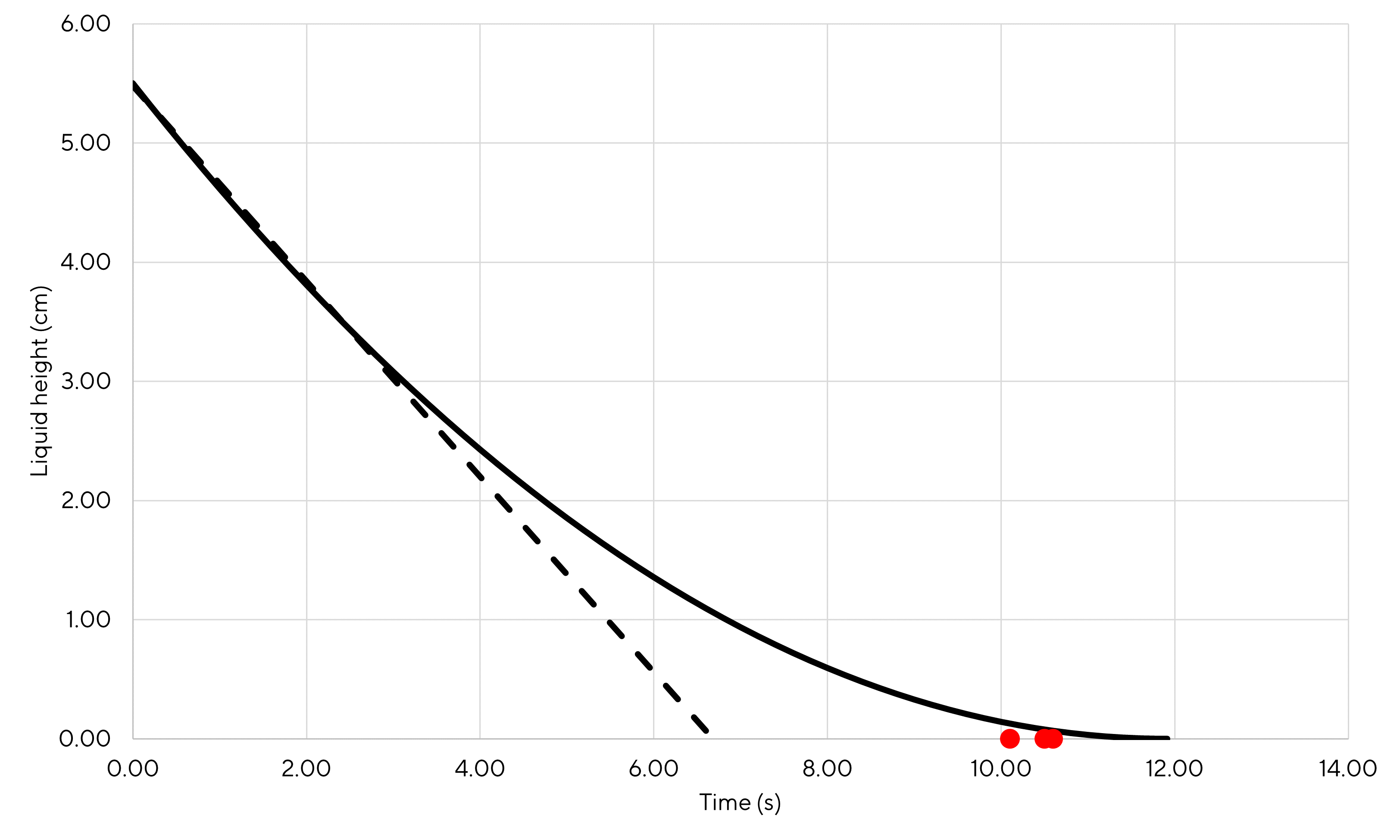
Figure 3.1: Liquid height with respect to time
The precise time to empty the cup to be obtained setting \(h=0\) in the previous equation and finding the associated \(t\) value:
\[\begin{equation} t_{end} = \frac{1}{\sqrt{\frac{g}{2h_0\left(\frac{S^2}{s^2} - 1\right)}}} \tag{3.1} \end{equation}\]Finally, one finds that the time to empty the cup according to the model is exactly 11.91 seconds.
What is also interesting with the model is the comparison between the liquid height velocity \(v_2\) and the liquid velocity at the cup hole \(v_1\). The liquid level velocity is defined as \(v_2=dh/dt\). One can either derive equation (2.10) with respect to time or just read equation (2.6)
\[\begin{equation} v_2=\frac{dh}{dt} = -\sqrt{\frac{2gh}{\left(\frac{S^2}{s^2}-1\right)}} \tag{3.2} \end{equation}\]Therefore:
\[\begin{equation} v_2\left(t\right) = -\sqrt{\frac{2g}{\left(\frac{S^2}{s^2}-1\right)}} \times \left(\sqrt{h_0} - \sqrt{\frac{g}{2\left(\frac{S^2}{s^2}-1\right)}} \times t\right) \tag{3.3} \end{equation}\]For \(v_1\), using equation (2.1), one can find that:
\[\begin{equation} v_1 = -\frac{dh}{dt} \times \frac{S}{s} \tag{3.4} \end{equation}\]Therefore:
\[\begin{equation} v_1 = \sqrt{\frac{2gh}{\left(\frac{S^2}{s^2}-1\right)}} \times \frac{S}{s} = \sqrt{\frac{2gh}{1-\frac{s^2}{S^2}}} \tag{3.5} \end{equation}\]So, finally:
\[\begin{equation} v_1\left(t\right) = \sqrt{\frac{2g}{1-\frac{s^2}{S^2}}} \times \left(\sqrt{h_0} - \sqrt{\frac{g}{2\left(\frac{S^2}{s^2}-1\right)}} \times t\right) \tag{3.6} \end{equation}\]Below is a comparison of the velocities with respect to time (absolute value of \(v_2\) is plotted to easier comparison as \(v_2\) is negative as it is defined). As indicated by the equations, \(v_1\) and \(v_2\) are linear with respect to time. One can see that the fluid velocity is approximately 100 times higher that the liquid height velocity during the whole process duration (typically 1 m/s vs 1 cm/s at the initial time). In fact, as show by equation (2.1) the ratio of the velocities is equal to the \(S/s\) ratio. According to the geometric parameters selected for this application, this ratio is equal to 112.5 which the exact ration between the two velocities once all calculations are performed (indeed very close to 100).
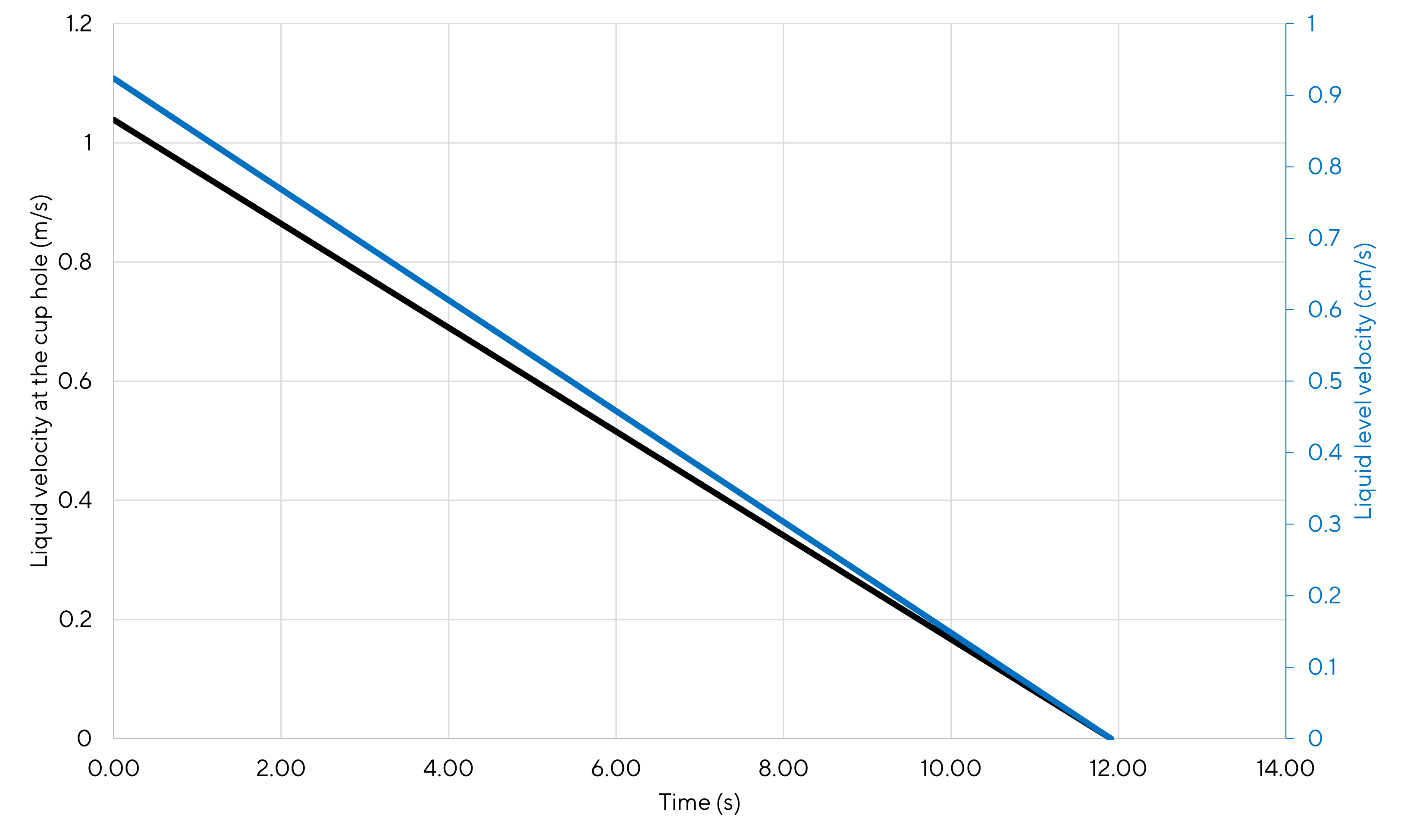
Figure 3.2: Velocities with respect to time